블로그 내용을 그대로 긁어다 붙였습니다. ^^;
http://ysymidi.blog.me/200000244189 에 정리되어 있는 내용이예요.
=====================================================================================
NerD 기판의 Side LED 납땜을 물어보시는 분들이 종종 있어서...
?
사진으로 간략히 정리합니다. 사진으로 보면 쉽게 이해가 됩니다.
?
?
Step 1

?
저항은 먼저 납땜이 되어 있어야합니다.
한쪽 동박에 넉넉히 납을 먹여주세요.
?
You must have the resistors soldered before you go further for soldering your SMD LEDs.
Then, apply enough solder on one of the two solder pads.
?
?
?
?
?
?
Step 2

?
납땜용 정밀 핀셋으로 칩엘이디를 집고 이렇게 옆으로 90도 돌려서(발광부가 바깥쪽을 향하도록) 납땜해 줍니다. LED는 극성이 있으니 주의하세요, 사진에서 LED뒷면 마크가 왼쪽을 향하고 있는 것 같지요? 그게 -를 향하고 있는겁니다. 기판에도 -가 실크 프린트되어 있는 것이 보이지요?
?
Make a solder joint on the right of your LED(if you are a lefty, you may solder the left pad first).
You need tweezers to do this.
Be careful: LEDs have polarity. SMD LED indicates its negative pole(GND, cathode) with arrow-like mark on its back.
Match the cathode of the LED to the GND(-) of the SMD LED soldering pad marked with silk print on the PCB.
Step 3

이제 남은 곳을 납땜해주면 됩니다. 여긴 쉬운데요... -극이 저항하고 쇼트(붙음)되면 사고납니다. 다량의 전류가 의도하지 않게 회로에 흘러버리기 때문에, 키보드가 오작동을 하게 됩니다.
웬만하면 루뻬 들이대고 전수검사 하시는 것을 권해드립니다.
?
All the rest is to make a solder joint on the other side of the LED.
It's easy but you have to be VERY CAREFUL not to make the two adjacent(cathode of the LED and its near solder pad of the resistor) solder pads bridged. If that happens, your circuit board would not work when LEDs of that channel are turned on.
I recommend you to take a close look with a loupe before you supply power to your board.
?
?
?
?
?
Other perspectives
?
?
Front view in Step 2
?
?

Front view in Step 3 when you have finished soldering a set of "AN" SMD LED.
?
?
?
?
?
?
Side view in Step 3 showing there is no BRIDGING between the LED and the resister.
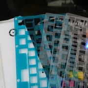
 허접 커스텀 첫번째 !!!!!
 nerd tkl 비키스타일 조립중입니다.